Pressure Ratings
Pressure ratings are identified in different ways. This following is for general guidance only.
Standard Dimension Ratio (‘SDR’)
The SDR is the ratio of pipe diameter to wall thickness. This is expressed as: and the SDR can be expressed as
SDR = D / s
where: D = pipe outside diameter (mm) and s = pipe wall thickness (mm). Thus, the SDR for 160 mm diameter pipe with a wall thickness of 9.5mm is 160/9.5 or 17 = SDR17. The outside diameter (D) is 17 times the thickness of the wall (s).
The higher the SDR rating, the thinner the wall, and the lower the pressure rating. A high SDR pipe has a low-pressure rating and a low SDR pipe has a high-pressure rating.
Pipe Series (‘S’)
Pipe series (‘S”) is a dimensionless number related to the nominal outside diameter and wall thickness of a pipe. The pipe series (‘S’) can be calculated as:
S = (SDR – 1) / 2
where S = pipe series. Thus, a 160 mm diameter pipe with a wall thickness of 9.5mm, SDR 17, has a Pipe Series number of (17 – 1) /2 or 8 = S8.
Nominal Pressure Rating (‘PN’)
The PN pressure rating comes from the French “Pression Nominal” the number indicated following the letters PN indicates the approximate pressure rating in bars. Note that 1 bar = 1×10⁵ pascals (Pa) = 0.1 N/mm2 = 100 kilonewtons /m2 = 10197.16213 mm of water = 0.986923 atmospheres (atm).
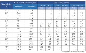
Class Rating
Class is a rating used in the Imperial BS 3505 standard.
Class C: 9 bar
Class D: 12 bar
Class E: 15 bar
BS EN 1452
ASTM D 1785 and ASTM D 2665
Maximum operating and required minimum bursting pressures at 73°F (23°C) for PVC pipes according ASTM D1785 “Standard Specification for Poly Vinyl Chloride (PVC) Plastic Pipes Schedules 40 and 80” are indicated in the table below:
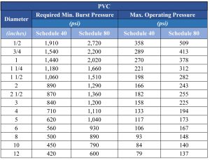
Key conversion: 1 psi (lb/in2) = 6,894.8 Pa (N/m2); 1 inch = 25.4 mm.
NB! The maximum operating pressures lowers as the temperature increases see below.
Effect of Temperature on Pressure Rating
uPVC pressure pipes are suitable for use at service temperatures up to 60˚C. However, we must take into consideration the design of the working pressure since this will be reduced as the ambient temperature increases.
Mechanical properties of uPVC are temperature dependent. Nominal working pressures are determined at 20˚C. For lower operating temperatures, the 20˚C ratings are used, even though properties such as tensile strength are greater. As the temperature decreases, it is advisable to take additional care to avoid impact damage as the impact strength decreases with temperature zero degree Celsius and below.
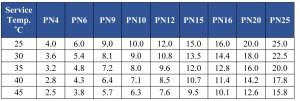
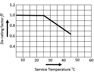
To compensate for operates temperature above 20˚C it is necessary to apply “de-rating factor” in the design. In the case of BSEN 1452 the de-rating factor (fT) for the service temperature to 45˚C can be determined from the graph below.
If we are considering a PN 15 pipe to work at 45˚C, the de-rating factor of 45˚C is 0.63, so that the maximum allowable operating pressure at 45˚C in the frequent use is 0.63 x 15 bar = 9.43 bar. Here the service period also plays a vital role in the design criteria. See below Table P7
For some applications, which need additional de-rating factor for e.g. more safety than the overall service (design) coefficient of 2 or 2.5 an additional factor (fA) can be chosen at the design stage.
The allowable working pressure in continuous use can be determined from the formula: (PFA) = fT x fA x [PN] Where: PFA is the allowable operating pressure; fT is the de-rating factor for the service temperature between 25˚C to 45˚C; fA is the de-rating factor related to the application; [PN] is the nominal pressure.
BS 3505
In compliance of BS 3505, the dimensional specifications under this standard are as follows:
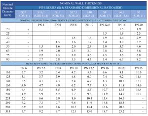
 BS EN 1452 – Metric
These pipes are manufactured confirm to BS EN 1452 for water supply under pressure range 6 to 25 bars. The dimensional specifications under this standard are as follows:
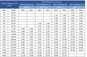
DIN 8062
The following table illustrates the dimensional specifications in compliance with DIN 8062 standard.
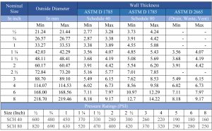
ASTM D 1785 / ASTM D 2665
The following table illustrates the dimensional specifications of ASTM D 1785 / ASTM D 2665 between Schedule 40, Schedule 80 and “Drain, Waste and Vent” pipes.